D flip flop circuit using hef4013b T flip flop circuit diagram, truth table & working explained T flip-flop circuit using 74hc74
Truth Table Of Sr Flip Flop Using Nor Gate | Brokeasshome.com
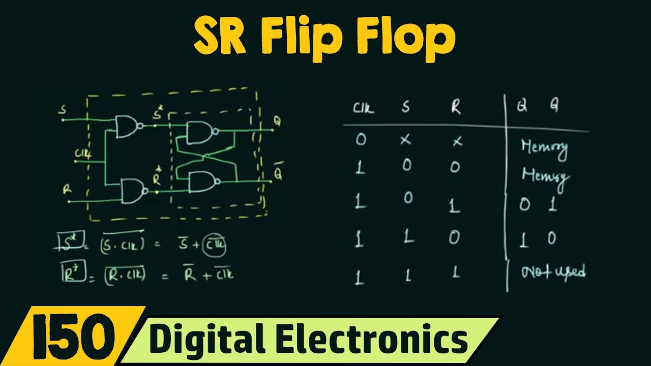
Truth table of sr flip flop using nor gate Flop flip truth table circuit using sr jk data circuits working 74hc00 binary inputs diy Sr flop flops logic neso truth circuit gates inputs electronics schemas latch convert
Logic diagram and truth table of sr : truth table of sr flip flop
Flip flop circuit table truth using flops working toggle state circuits clock because call theseJk flip flop circuit using 74ls73 Flip flop truth table circuit symbol flops working diagram clock inputs output circuitdigest visit circuitsJk flip flop diagram & truth tables explained.
Flip flop jk flops circuits 74hc00 clk latches datasheet termedT flip-flop circuit using 74hc74 Flop sr truth nor jk latch logic circuitFlip flop jk circuits.

Flip flop jk truth diagram flops sr tables explained table circuit rs two its example diagrams discussed
.
.

Logic Diagram And Truth Table Of Sr : Truth Table Of Sr Flip Flop

T Flip-Flop Circuit using 74HC74 - Truth Table and Working

T Flip Flop Circuit Diagram, Truth Table & Working Explained

T Flip-Flop Circuit using 74HC74 - Truth Table and Working

Truth Table Of Sr Flip Flop Using Nor Gate | Brokeasshome.com

JK Flip Flop Circuit using 74LS73 - Truth Table
